
The following sections are ordered according the steps needed to create a component diagram and describe each creation step in detail.
 Assigning the Diagram Name
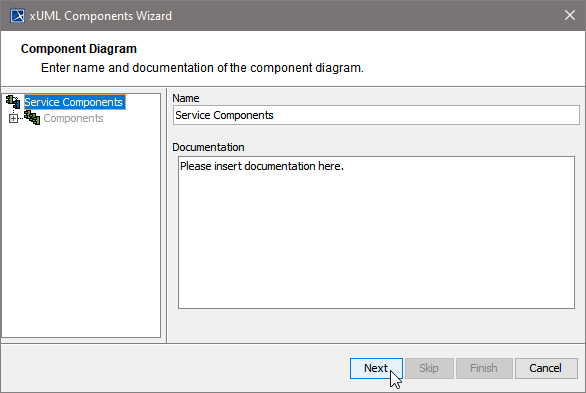
After starting the Components Wizard, the first dialog opens, and you are prompted to enter the name of the component diagram.
You may use the default name suggested or enter a descriptive name. Changing the name will change the name of the top most tree node (marked in blue) in the navigation panel.
Click Next to proceed or Cancel to abort:
The Components Wizard can be canceled any time. After clicking cancel, the Components Wizard prompts for confirmation:

 Defining the Composite
With the next step, you define the service composite. The service composite represents the repository of the Web service and will contain all necessary configuration information.
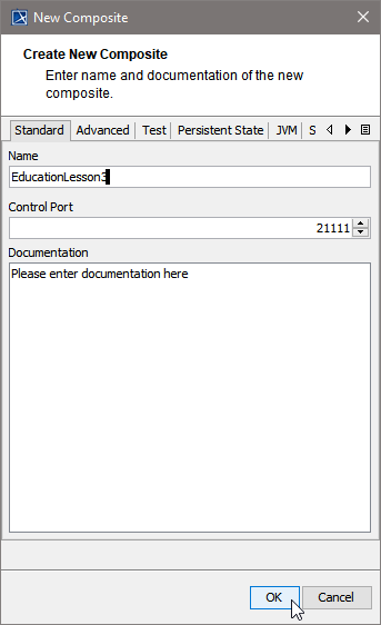
Clicking Next after having assigned the diagram name will bring you directly to the following dialog. Create the service composite here.
Assign a name to the composite. In the field Control Port, enter an unused port number (the value needs to be between 20'000 and 29'999).
Special characters and blanks are not allowed for composite names.
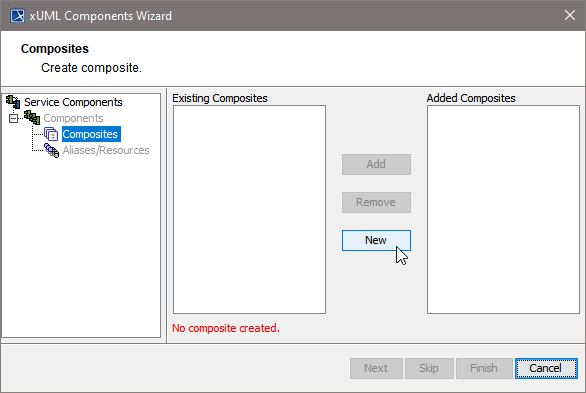
In case you accidentally clicked the Cancel button, the Create new Composite window can be re-opened by clicking the New button.
The Create New Composite dialog contains four more tabs.
Advanced Tab
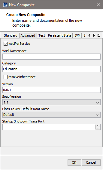
Click to read what you can configure on the Advanced tab (show | hide)
On the Advanced tab of this dialog, you can configure advanced composite settings as tagged values to the composite.
|
Tagged Value |
Description |
|---|---|
|
wsdlPerService |
If true (default=false), each xUML service gets its own WSDL file. Additionally, all XML Schema elements and types having the same namespace are put into one schema file. These schema files are imported into the WSDLs to be shared among them. In this case it is also possible to mix RPC/soap-encoded services with Document/literal services. |
|
WSDL Namespace |
Target WSDL namespace of the generated WSDL file. Relevant only, if wsdlPerService is false (this is the default). |
|
Category |
Optional category to group similar xUML services. |
|
resolveInheritance |
deprecated If true, the inheritance hierarchy is resolved into flat messages. Setting resolveInheritance to true is deprecated, because this will generate a different output structure than modeled. It also has hidden requirements to the element uniqueness. |
|
Version |
A service version number. This service version is visible in service context on the Bridge. |
|
Soap Version |
Specify the version of the SOAP protocol you want to use with the service. |
|
Class To XML Default Root Name |
Specify which name to assign to the XML root element upon serializing. This setting can be overridden by using XML composer options as described on classToXML() Operation. Refer to XML - UML Class Mapping for more information on the topic of XML serialization. |
|
Startup Shutdown Trace Port |
Default port for tracing startup or shutdown activities is 30000. You can change this default here, if necessary. |
For more information on these tagged values refer to Frontend Components.
Test Tab
Click to read what you can configure on the Test tab (show | hide)
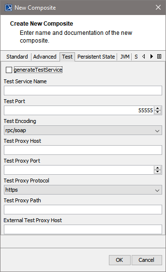
Specify the test settings on the Test tab.
|
Tagged Value |
Description |
|---|---|
|
generateTestService |
Enables or disables testing. If true, a test SOAP service will be generated for all <<E2ETestable>> classes. |
|
Test Service Name |
Defines the name of the generated test service. |
|
Test Port |
Defines the number of the test service port. |
|
Test Encoding |
Defines the encoding of the test SOAP operations. rpc/soap is recommended, because this matches well with the semantics of UML operations. If this value is set and other services of the composite have different encodings, the tag wsdlPerService must be set to true. |
|
Test Proxy Host |
Specifies the deployment host. |
|
Test Proxy Port |
Specifies the proxy port the test service is listening to. |
|
Test Proxy Protocol |
Specifies the used protocol. |
|
Test Proxy Path |
Specifies the part of the overall URL that is mapped to the actual host name and port. If this tagged value is used, the modeler must ensure, that this value is unique within the proxy. |
|
External Test Proxy Host |
Specifies the host name as seen by the client. If a server certificate is used, it must be issued for this name.If this value is not set, the name of the node hosting the proxy is being used. |
For more information on testing in general refer to xUML Service Model Debugging, Testing and Quality Assurance (QA) Concepts.
Persistent State Tab
Click to read what you can configure on the Persisten State tab (show | hide)
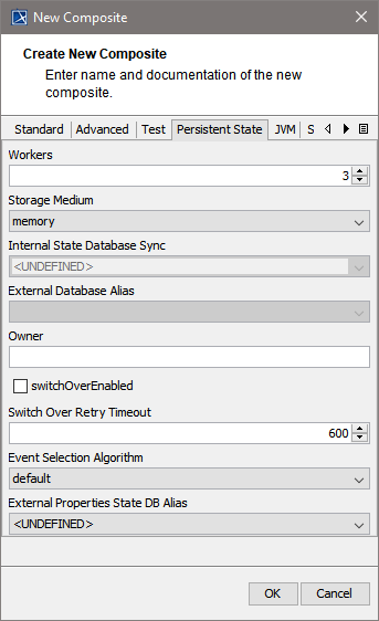
Using Persistent State features in the xUML service, you can make corresponding adjustments on the Persistent State tab, and configure the persistent state engine.
|
Tagged Value |
Description |
|---|---|
|
Workers |
Workers defines the maximum number of parallel threads used to process pending events. The default setting is 5, which is used if none or 0 workers are configured. The implications of more or less workers are discussed in Performance Considerations of Persistent State. Each active worker requires one license slot (concurrent connection) to process activities. For more information on licensing and concurrent connections, refer to License for Running xUML Services. |
|
Storage Medium |
Storage Medium defines where the persisted data and additional information like pending events and current states are kept. See section Data Storage for a discussion of the options.
|
|
Internal State Database Sync |
Internal State DB Synch defines the level of file system synchronization performed on the internal persistent state database. For production setup, we recommend using FULL synch. |
|
External Database Alias |
Runtime 2019.8 Specify the database alias of the external database you want to store external persistent data to.
|
|
Owner |
Owner specifies the owner of the persistent state objects. Default owner (used when no divergent owner is specified) is the xUML service name, which is unique on each node instance. |
|
Switch Over Enabled |
This flag enables the automatic fail over mechanism for clustered persistent state databases. If the persistent state database becomes inoperative, the xUML Runtime will try to open a connection to compensatory database of the cluster. See also option Switch Over Retry Timeout. This option is available for clustered Oracle databases only. |
|
Switch Over Retry Timeout |
During fail over, the xUML Runtime will try to create a new database connection to a compensatory database (see Switch Over Enabled). If this fails, the xUML Runtime will try to open a new connection every second until the timeout (in seconds) is reached. Default is 600 seconds. |
|
Event Selection Algorithm |
Runtime 2019.2 The xUML Runtime processes the persistent state events in a defined order. Select the event selection algorithm the xUML Runtime should use to define this order of events.
Services using this tagged value (all options but the default <not specified>) will not start on a Runtime below 2019.2. |
|
External Properties State DB Alias |
Runtime 2019.8 Specify the database alias of the external database you want to store external persistent data to.
|
For more information Persistent State Components.
JVM Tab
Click to read what you can configure on the JVM tab (show | hide)
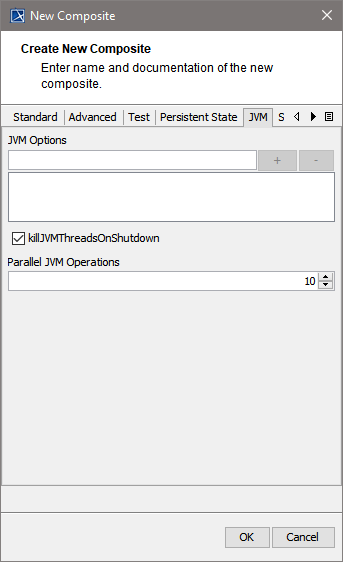
Using Java services in the xUML service, you can specify the JVM options on the JVM tab.
|
Tagged Value |
Description |
|---|---|
|
JVM Options |
Java Virtual Machine options. The option strings has one of the following formats: "-D=...", "-X...", "_...", The system properties java.class.path and java.library.path are set by the model compiler and can not be overridden in the model. |
|
killJVMThreadsOnShutdown |
If threads are still running on shutdown they are killed. |
|
Parallel JVM Operations |
Number of parallel open JavaVM threads within the runtime. Default: 100. If the limit is reached, the runtime tries for 60 seconds to obtain a free JVM thread. If it does not succeed, an error (JAVAADLM/19) is thrown. |
For more information on Java Components refer to Modeling the Java Components.
Click OK to proceed.
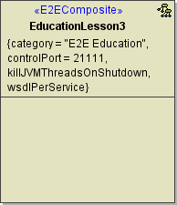
Up to this point, you have defined the xUML service component EducationLesson3.
In the customization panel, you can find the new xUML service component (e.g. EducationLesson3) in the list of added composites on the right side.
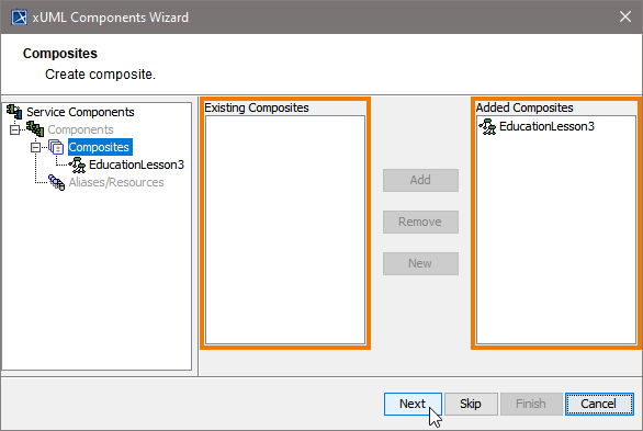
The left side of the customization panel contains available components, classes, or interfaces. The right side always contains the used components.
Click Next to proceed.
 Defining the Frontend Service
In the next step, you define the frontend service that will be part of the xUML service.
Clicking Next after having defined the composite will bring you directly to the following dialog. Add a frontend service here.
Select a service type from the list:
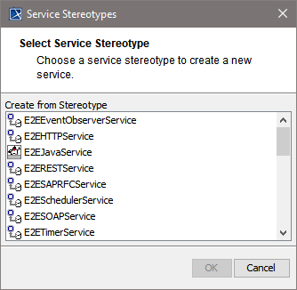
In other cases, e.g. if you want to add additional services, you can open the above dialog by clicking New on Services level of the tree:
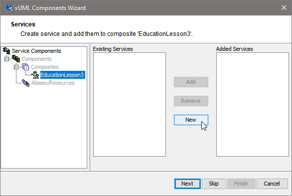
All possible frontend service stereotypes are listed:
|
|
|
This example shows how to define a Web service. Select the service stereotype E2ESOAPService.
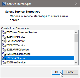
Proceed with OK.
Now, customize the service artifact.
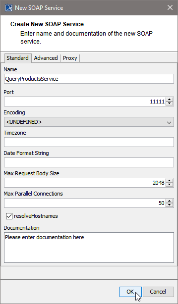
|
Tagged Value |
Description |
|---|---|
|
Name |
Assign a Name. |
|
Port |
Assign a Port, to which the SOAP service is listening (the value needs to be between 10'000 and 19'999). |
|
Encoding |
Select an encoding. See Encoding of SOAP Operations for more information on SOAP encoding of xUML services. |
|
Timezone |
Time zone string as specified in the time zone appendix. timezone is used to print DateTime expressions. |
|
Date Format String |
Date formatting code as listed in Date and Time Formatting. If nothing is defined, the XSD standard is used. |
|
Max Request Body Size |
Runtime 2021.2 Specifies the maximum size of the request in KB (1 KB = 1024 Bytes). This can be used to prevent DoS or similar attacks. When the payload of the service exceeds the given maximum, incoming request are rejected. |
|
Max Parallel Connections |
Maximum number of requests that can be processed in parallel. |
|
resolveHostnames |
Automatically resolve IP addresses to domain names. |
The Create New SOAP Service dialog contains two more tabs.
On the Advanced tab, you can specify the following settings:
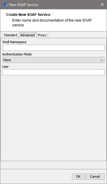
|
Tagged Value |
Description |
|---|---|
|
Wsdl Namespace |
Specifies the target namespace of the generated WSDL file. This is relevant only, if wsdlPerService in the xUML composite is true (see Frontend Components). |
|
Authentication Mode |
Defines the authentication mode to be used with this SOAP service.
Independent of the authentication mode, the user is found in the principal object if the authentication succeeded. |
|
User |
Specifies user and password for the use of HTTP Basic authentication. |
For detailed information on these tagged values refer to SOAP Service Reference.
On the Proxy tab, you can specify the proxy details.
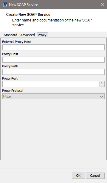
|
Tagged Value |
Description |
|---|---|
|
External Proxy Host |
Specifies the host name as seen by the client.
|
|
Proxy Host |
Specifies the host for the proxy deployment. If localhost is used, the proxy will be created on the same host the service is deployed to. Use a dedicated host, if you want to run your proxy on a different host of the same Bridge domain.
See also externalProxyHost. |
|
Proxy Path |
Specifies the part of the overall URL that is mapped to the actual host name and port. If proxyPath is used, the modeler must ensure that this value is unique within the proxy.
|
|
Proxy Port |
Specifies the port the proxy is listening to. |
|
Proxy Protocol |
Specifies the used proxy protocol. |
For detailed information on these tagged values refer to SOAP Service Reference.
Proceed with OK.
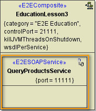
Now, in the component diagram the service component is placed within the service composite component.
In the customization panel on the right, you will find the new service (e.g. QueryProductsService):
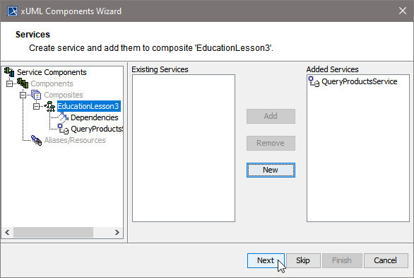
Click Next to proceed.
 Defining the SOAP Service Interface
In the next step, you will define the interface of the SOAP service. Through this interface, the Web service is accessible from the outside world.
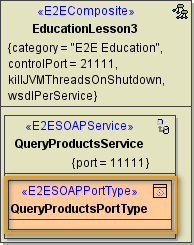
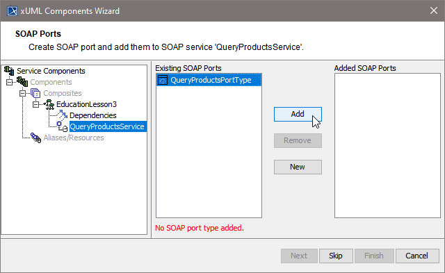
The Components Wizard lists all port type classes on the left. Select a port type and click Add to add the port type to the composite.
In the following dialog, assign a name to the port type or use the default name suggested.
Special characters and blanks are not allowed for component names.
-
Provide a Namespace if necessary.
-
Provide a path, if you want to make this component independent of the package structure. Without a given path, port types are identified by port type name and package URL.
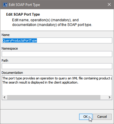
Proceed with OK.
In the artifact part oft the customization panel, you will find the added port type QueryProductsPortType .
As an interface can only be used once in a composite, the port type QueryProductsPortType is not displayed anymore in the SOAP Port Types list on the left.
Each port type class (representing the interface of the SOAP service) can only be used once in a composite.
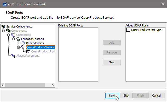
Click Next to proceed.
In the Customized Artifacts part of the tree panel, the xUML service is selected again to give you the option to define further frontend services (see Defining the Frontend Service).
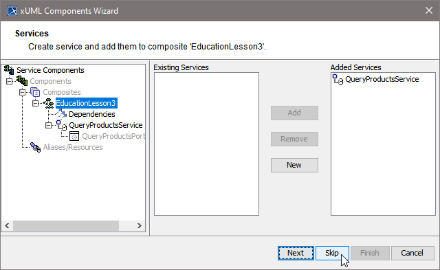
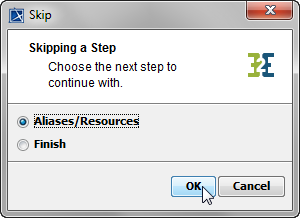
If you do not need any further elements, click Skip.
For definition of Backend Services (Aliases/Resources) see below (Defining Backend Aliases).
For Finishing the Components Wizard see Finishing the Components Wizard.
 Defining Backend Aliases
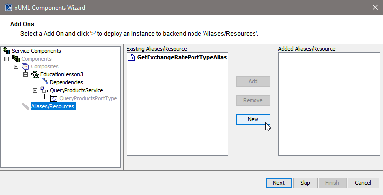
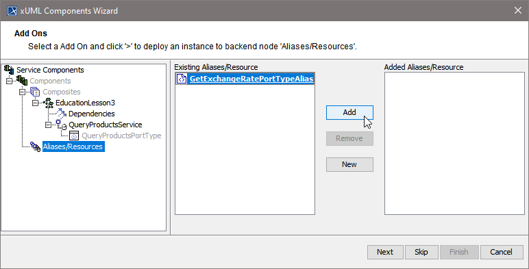
In this step, backend aliases are defined. The Components Wizard provides predefined Backend Components.
Click New to create a new backend alias ...
...or select an existing alias and click Add to add it to the component diagram.
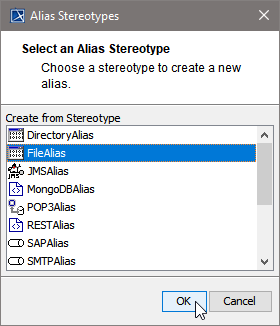
For adding a new alias, choose one of the following possible backend service stereotypes:
-
FileSystemAlias
-
JMSAlias
-
POP3Alias
-
SAPAlias
-
SMTPAlias
-
SOAPAlias
-
SQLAlias
-
URLAlias
Choose a backend alias stereotype from the list of available stereotypes, e.g. FileAlias and click OK.
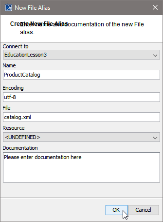
Assign a name to the alias or leave the default name suggested.
Specify File Name and Path, or, if you wanted to read data from an imported resource, select the resource from the Resource drop-down box instead.
Click OK.
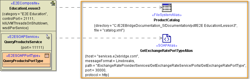
In right part oft the customization panel, you will find the new file system alias (e.g. ProductCatalog).
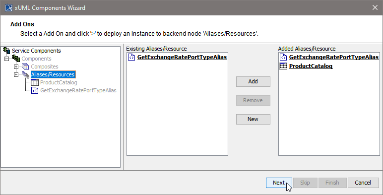
Click Next.
 Finishing the Components Wizard
This is the final step of the Components Wizard where you confirm to draw the component diagram. If the definitions are not complete yet, you can select an element node in the tree panel and add further UML elements to the diagram.
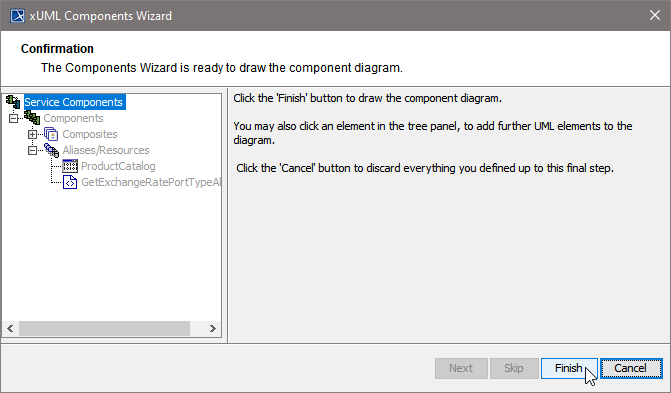
The Components Wizard generates the component diagram. If no errors occurred, it is necessary to save the model. On saving, the deployment data of the Model Compiler gets refreshed and you can proceed with e.g. compiling the model.